Arduino & Arduino IDE
Arduino is an open-source electronics platform that consists of both hardware
and software components. Arduino includes a series of microcontroller boards
that are equipped with various input and output pins. The Arduino IDE
is a programming environment used to write, compile, and upload code to the
Arduino board. It uses a programming language based on C/C++ code to write
sketches. Arduino Sketches are the program files with the .ino extension that
contain Arduino code. Arduino code is written with C/C++ language syntax and
structure and uses distinct methods and functions.
- The Arduino IDE can be downloaded at https://www.arduino.cc/en/software.
Tinkercad
Tinkercad can be used to program and simulate a virtual Arduino microcontroller
circuit online. Tinkercad is an online platform that allows users to design and
simulate 3D models. Tinkercad includes a circuit simulation feature that allows
users to design and simulate electronic circuits.
- Create a Tinkercad account at https://www.tinkercad.com.

Build the Circuit
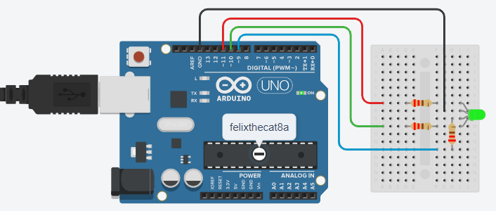
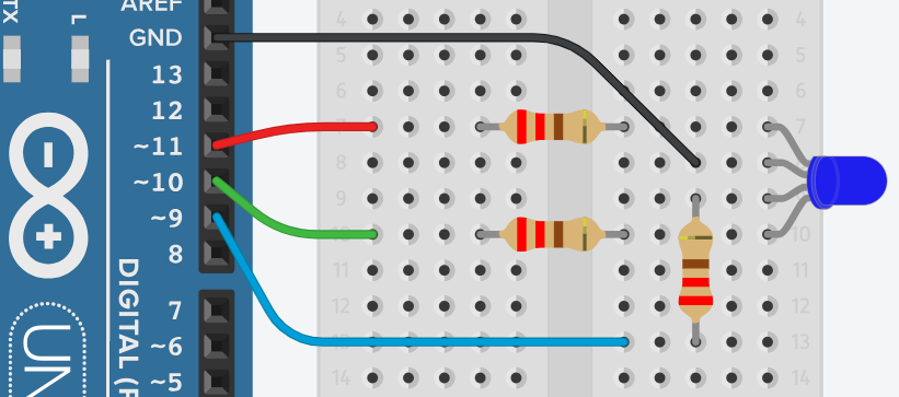
This circuit will require an Arduino Uno R3 board, an RGB LED, three 220Ω resistors, a breadboard, and jumper wires.

Using Tinkercad
- If using Tinkercad, click on "Create" and select "Circuit" from the drop-down menu.
- This will open a new workspace so that you can drag-and-drop the components needed.
Create an Arduino Sketch
Open the Arduino IDE and insert the code that is shown.
Using Tinkercad
- If using Tinkercad, click on "Code" button on the top right area of the screen.
- Change the Edit Mode from "Blocks" to "Text" by clicking on the selector.
/* rgbLED.ino */
/* Requires pins that support PWM (denoted by ~) */
const int redPin = 11, greenPin = 10, bluePin = 9;
bool commonAnode = false; // set true for common anode
void setup() {
    pinMode(redPin, OUTPUT);
    pinMode(bluePin, OUTPUT);
    pinMode(greenPin, OUTPUT);
}
void loop() {
    setColor(255, 0, 0); // Red
    delay(1000); // every 1 sec (1000 ms)
    setColor(255, 255, 0); // Yellow
    delay(1000);
    setColor(0, 255, 0); // Green
    delay(1000);
    setColor(0, 0, 255); // Blue
    delay(1000);
    setColor(255, 0, 255); // Violet
    delay(1000);
}
void setColor(int redValue, int greenValue, int blueValue) {
    if (commonAnode) {
        redValue = 255 - redValue;
        greenValue = 255 - greenValue;
        blueValue = 255 - blueValue;
    }
    analogWrite(redPin, redValue);
    analogWrite(greenPin, greenValue);
    analogWrite(bluePin, blueValue);
}
Upload the Sketch to the Board
- Connect your Arduino Uno board to the USB port.
- Go to "Tools", then "Board", and select "Arduino Uno".
- Go to "Tools", then "Port", and select "COM#:Arduino Uno".
- Go to "Sketch", and select "Verify/Compile" or click the checkmark button.
- If there are any errors, review the code, fix the errors and compile the code again.
- Go to "Sketch", and select "Upload" or click the arrow button.
Using Tinkercad
- If using Tinkercad, click on "Start Simulation" button on the top right area of the screen.
- If the code has any errors, the code will not run and the errors will be highlighted in red.